The perfect global grid system is impossible; HexGeoGrids.jl
An exploration of grid system design space, and an alternative to the typical options like H3 and S2.
Aggressively brief background on grid systems
A global grid system is a way of partitioning the Earth’s surface into smaller regions, often known as cells. Depending on your perspective and preferred nomenclature, global grids may be closely related to or the same as discrete global grids, [geo]spatial indices, geocode systems, etc. The most well known examples are probably Uber’s H3, Google’s S2, Geohash, and Open Location Code.
From my day job at Zoba, I’m most familiar with grid systems as a convenient tool for splitting a city into cells of approximately uniform shape and size; these cells become a unit of analysis. For example, if you want to characterize the spatial distribution of shared bikes over a city, it’s natural to simply count how many bikes are in each grid cell. In fact, many of our analyses and optimizations are at the cell level: we count vehicles and rides by cell, estimate and forecast demand by cell, estimate the prevalence of mobility competition by cell, and so forth.
It’s against the law to write a blog post about maps without liberal use of visuals, so let’s get started.1 I’ll use H3 as an example, both because it’s something of a de facto standard and because it’s easy to use. These are probably related. Here’s how H3 divides North America into very coarse cells:
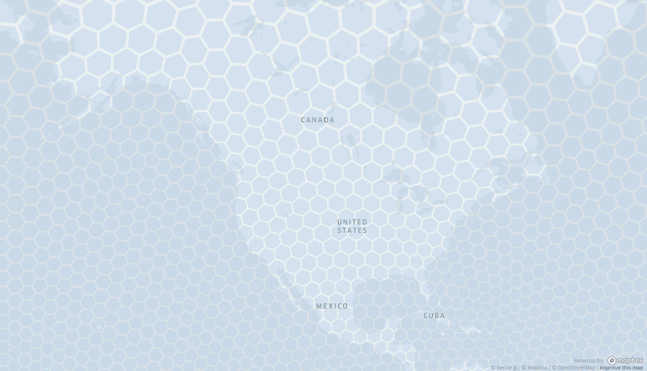
(The majority of the apparent distortion in cell size and shape comes from the web Mercator projection used in Kepler and approximately everywhere else on the web.)
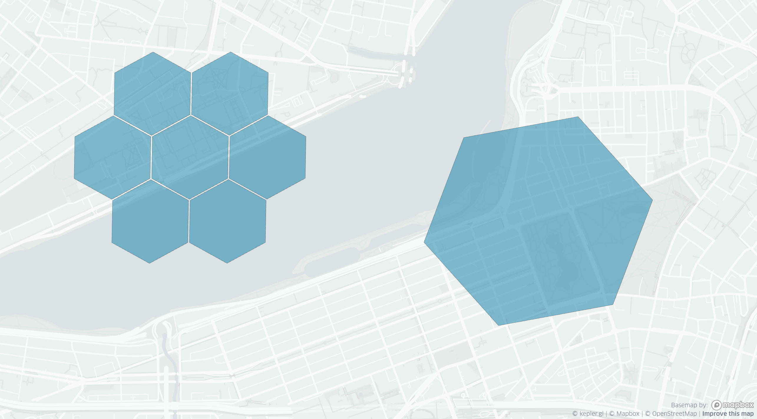
Pretty much every grid system offers multiple resolutions. High resolutions (or precision levels, or granularities) correspond to partitioning the Earth’s surface into many small cells; low resolutions correspond to a few big cells. For example, here’s Boston with two sizes of H3 cells. I’ve plotted a large cell by the public garden and seven smaller cells by MIT. Collectively, the seven small cells have the same area as the large cell.
Grid system design considerations
Creating a global grid system requires lots of design decisions: how is the Earth’s surface (not flat, despite my best efforts) projected to flat surfaces? What kind of planar grid overlays those flat surfaces? Or maybe a projection-free grid is possible? How are cells shaped and oriented? What resolutions are available, and how do they relate to each other?
The best design choices are surely context dependent, but we can list some reasonable desiderata for a general purpose global grid system:
- All cells at a given resolution have equal size, or at least nearly equal.
- All cells have the same shape, and that shape is close to a convex regular polygon.
- All neighbors of a given cell are at the same distance from that cell.
- Multiple cell resolutions are available, and each cell is perfectly partitioned by cells of a finer resolution.
- The grid system covers the entire earth, and each point on the earth is in exactly one cell of a given granularity. In other words, the grid system is not made up of overlapping mutually-incompatible subgrids.
Unfortunately, these design goals conflict with each other. Let’s try to design a grid system that satisfies them. Start with desideratum #2, that cells are regular polygons. The Earth is approximately spherical, and up close spheres look like planes. So our cells must tile the plane. If our cells are regular convex polygons, that means cells must be equilateral triangles, squares, or regular hexagons.
Triangles and squares violate goal #3 by having different flavors of neighbors. For example, a square cell (in green below) has both edge-neighbors (red) and corner-neighbors (blue); the corner neighbors are much farther away:
Triangles are even worse, with three types of neighbors. Hexagons, on the other hand, have only one kind of neighbor. In a hexagonal tiling of the plane, each hexagon cell (green) has six neighbors (blue), which correspond to the cell’s six edges and are each at the same distance away:
So maybe we should use hexagons? While I do believe hexagons are the best choice for general use, they’re not perfect either. In particular, they don’t subdivide perfectly. With square[-ish] cells, each cell can be perfectly subdivided into 4 similar sub-cells. But hexagons can’t be subdivided into similar smaller hexagons; the best strategy I know of comes from H3, which approximately divides each hexagon into 7 smaller rotated hexagons.
So we’ve reached a contradiction. Regular polygon grid cells implies triangle, square, or hexagon cells. Each cell having just one kind of neighbor implies hexagonal cells, but each cell subdividing nicely implies not hexagonal cells. ⇒⇐
Maybe we shouldn’t have been using convex regular polygons? There are definitely exotic plane tiling schemes that don’t rely on regular polygons, but regular polygons are important because they minimize the perimeter to area ratio. One of many reasons this is important: location data is often imprecise. Let’s say you know locations only up to ± 10 meters, maybe due to GPS limitations. Then any time you think a point is less than 10 meters from a cell boundary, you should be worried that the point is actually in a neighboring cell. To minimize this situation, we’d want to minimize the perimeter to area ratio, which pushes us towards regular polygons. For example, consider a very spiky rhombus type shape: almost the whole area is near the boundary.
There are other subtle tensions between these five goals. Because the Earth is not flat, projecting the earth to a [collection of] flat spaces does involve some distortion, even for very clever projections such as those used by S2 and H3. These distortions will end up creating some variability between cells: not all cells will be the same size and shape. For example, even though H3 uses a very clever projection, at each resolution the largest cell in the world has area about twice that of the smallest cell. (Nearby cells have approximately the same area.) Check out some measurements and a cool visualization which reveals the projection structure.
S2 and H3
Google’s S2 and Uber’s H3 navigate the inevitable design tradeoffs slightly differently:
S2 projects the Earth’s surface to a cube, which corresponds to dividing the surface into six square-like shapes bounded by geodesics. Each square-like shape is then recursively divided into smaller squares. This strategy gives cells which are perfectly partitioned by cells at a higher resolution, but comes with the expected downsides of square-ish cells: different flavors of cell neighbors, higher perimeter/volume ratio than a hexagon would have, etc. In some parts of the world, the cells assume a more rhombus like shape, I think. I’m not sure how cell area varies over the world.
H3 projects the Earth’s surface to an icosahedron and then does a soccer-ball type pentagon and hexagon tessellation. At every resolution there are exactly 12 pentagons, and the icosahedron orientation is carefully chosen to put all 12 pentagons in the oceans. So unless you’re using very coarse cells or doing world-wide ocean mapping, in practice all cells you encounter will be hexagons. The carefully chosen projection orientation means that the orientation of individual hex cells is beyond the user’s control.
As we’ve seen, hexagons have nice neighbor properties but don’t subdivide cleanly. Also, each H3 resolution level changes hexagon area by a factor of 7 (i.e. a hexagon cell is approximately subdivided by 7 smaller cells at one resolution higher). This means the user has quite little control over cell size, especially because of the aforementioned variability in cell size at a given resolution.
Relaxing the global grid criterion
Recall the 5th desideratum from above:
The grid system covers the entire earth, and each point on the earth is in exactly one cell of a given granularity. In other words, the grid system is not made up of overlapping mutually-incompatible subgrids.
This requirement is entirely reasonable; consider what happens if we relax this constraint and allow our grid system to be a collection of overlapping grids, each with sub-global coverage. Then a given point on the Earth’s surface may be in multiple cells belonging to multiple subgrids; subgrids have boundaries, meaning that a cell near the boundary may not have any neighbors; there may be discontinuities between grids, etc. Potentially nasty stuff!
On the other hand, many of the inevitable tradeoffs in global grid design arise exactly because of the single-global-grid criterion: the Earth’s surface is not flat → the surface must be projected to a flat space → distortion and irregularities occur.
Depending on your use case, it may be totally irrelevant to you whether your grid system is a single global grid. This is certainly the case for me at my day job. At Zoba we use grids to model mobility networks and dynamics in one city at a time. Even the spatially largest cities are quite small compared to the curvature of the Earth; at city scale, the Earth is approximately flat. So if I’m using a grid system to model, say, Boston (where I live), I don’t particularly care whether that grid system is built on a clever projection. If my grid system only extends as far as the Rocky Mountains or the middle of the Atlantic Ocean or has some noticeable distortion in northern Canada—totally fine.
HexGeoGrids.jl
I built a proof of concept geographic grid package to explore what’s possible when we ignore the global grid requirement. The world is big so I’m sure somebody has done this before, but I’m not aware of a widely used grid system which makes the same set of tradeoffs I have. I should also add a disclaimer that the code is solidly…fine…and while I’d be delighted for you to look at or copy it (MIT license), I strongly advise against using it as-is for any important work or production systems.
HexGeoGrids.jl (GitHub) is a Julia package defining a large set of overlapping hexagonal grids, as well as some basic utilities for working with such grids. Compared to H3, the main advantages of HexGeoGrids are:
- Grid cells can have nearly arbitrary size: integer edge lengths between 1 and 65,535 meters are supported. H3 only lets the user vary cell area by factors of 7.
- Grid cells are regular hexagons, and over supported grid areas, grid cells are consistently sized and nearly distortion free. H3 cells vary in size.
- Grid cells have a consistent alignment: north-aligned flat-top hexagons, which makes grids look extra nice in typical web Mercator maps. H3 cell alignment is inconsistent.
These features come at a cost:
- There is not a single global grid, but instead many overlapping subgrids. Each cell must identify both the subgrid it belongs to and its coordinates within that subgrid.
- Subgrids have minimal distortion and consistent alignment only up to about the size of a small country (or medium sized US state), and only exist at all up to about the size of a continent. No global grid exists.
- HexGeoGrids isn’t a well maintained and widely used package. In fact, I do some hacky things and am sure anybody who knows more about geodesy than me would be horrified.
Examples
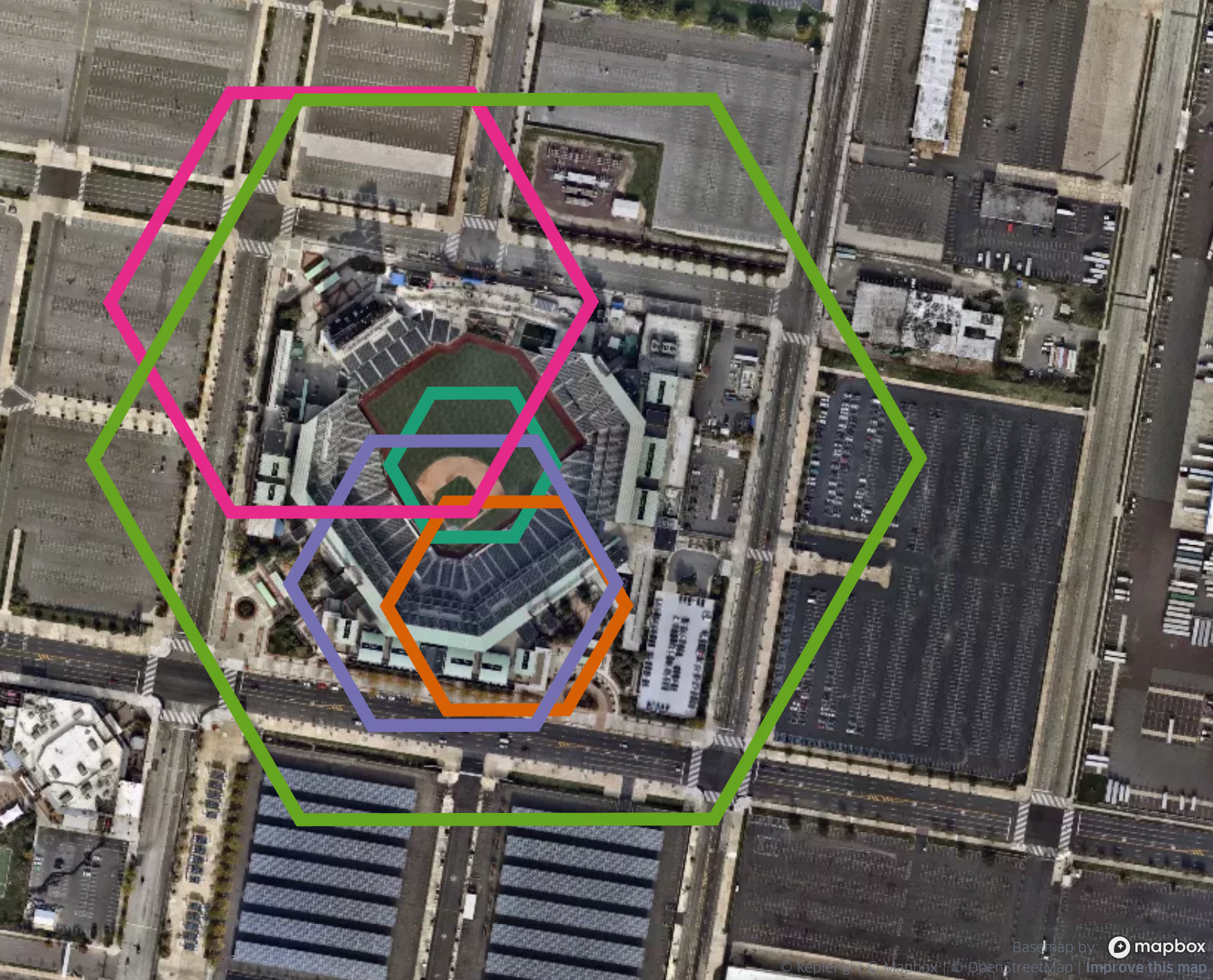
The pitcher’s mound of Citizens Bank Park, Philadelphia, contained in cells of various sizes:
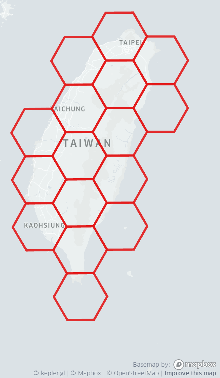
The main island of Taiwan covered in cells with edge length 40 kilometers:
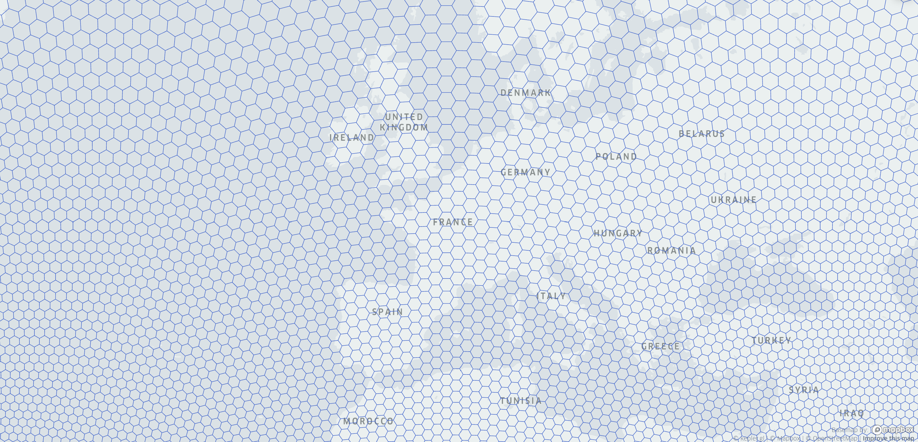
Europe covered in grid cells with 60km edges, with a grid centered on Paris: note the distortions and how hex alignment changes. The apparent tendency of hexagons to get larger the further north you look is just typical web Mercator size distortion by latitude. But observe how the hex cells rotate and shrink slightly as you look east or west of Paris; this effect is “real,” not just a map distortion.
How it works
HexGeoGrids defines both HexSystems and HexCells. A HexSystem is a grid that covers a part of the Earth; a HexCell is, shockingly, a cell in a particular system. Think of a HexSystem like
struct HexSystem
    center_lon::Int
    center_lat::Int
    size::UInt16
end
So a HexSystem defines a center point and the edge length in meters of HexCells in that system. You may note that the requirement that center points have integer lat/lon puts possible center points close together near the poles and far apart in more equitorial regions. If we call the current HexGeoGrids v0.1.0, a great v0.2.0 feature would be smarter distribution of possible center points over the surface of the Earth. I don’t want to simply allow floating point center coordinates, because it’s really convenient for index encoding if there are less than 2^16 possible centers.
A HexCell simply wraps a HexSystem and a hexagon coordinate, the latter of which is defined in my fork of Hexagons.jl. For example,
HexCell(
    HexSystem(1, 2, 3),
    HexFlatTop(0, 0)
)
is the flat top hexagon with axial coordinates (0, 0) in the HexSystem centered at the point with (lon, lat) = (1, 2) and edge length 3 meters. CoordAxial(0, 0) is the hexagon origin, so this HexCell is centered at (lon, lat) = (1, 2).
Right now, I’ve hard-coded that all HexSystems use flat top hexagons; a good v0.2.0 feature would be allowing pointy top as well, or even arbitrary orientation.
Mapping from longitude-latitude space to hexagon space works via an intermediate projection to Cartesian space. For this projection, I use the Universal Transverse Mercator coordinate system; the projection is handled out of the box by Geodesy.jl. The UTM coordinate system divides the Earth’s surface into longitude-narrow zones, each stretching from pole to pole. A good explanation of UTM coordinates is beyond the scope of this post and perhaps the span of my abilities. But for our purposes here…
UTM coordinates are Cartesian and in units of meters. The x axis is E-W, and the y axis roughly corresponds to north. (People who know about geodesy, start cringing extra hard now.) Best I can tell, for any point with longitude == 3 mod 6, i.e. halfway between the east and west edges of a UTM zone, the UTM y axis perfectly corresponds to north. Observe that in the Cartesian plane, lines parallel to the y axis don’t converge. But on Earth, lines pointing N/S do converge—at the poles. E.g. imagine you and me standing on the equator, 1 kilometer apart. We both start walking straight north. By the time we’re at latitude = 60°, we’re only about half a kilometer apart. So, since UTM lines parallel to the y axis don’t converge, they must veer slightly away from true north near the edges of UTM zones and away from the equator.
To make sure hexagons are nearly north aligned, HexGeoGrids shifts a HexSystem’s longitude to be congruent to 3 mod 6 before UTM projection; the opposite shift is performed when transforming back.
So, mapping a (lon, lat) tuple to a hexagon in a HexSystem looks roughly like:
function to_hex_cell(lon, lat, hs::HexSystem)
    shift = 3 - mod(lon, 6)
    lon_point, lat_point = lon + shfit, lat
    proj_to_utm = UTMfromLLA(hs.utm_zone.zone, hs.utm_zone.isnorth, wgs84)
    utmz_hexsystem_center = proj_to_utm(hs.center_lon + shift, hs.center_lat)
    utmz_point = proj_to_utm(lon_point, lat_point)
    relative_x, relative_y = utmz_point.x - utmz_center.x, utmz_point.y - utmz_center.y
    return HexCell(
        hs,
        Hexagons.hex_containing(relative_x / hs.size, relative_y / hs.size)
    )
end
Getting (lon, lat) coords from a HexCell, whether vertices or the center point, inverts the process. I haven’t much tuned for performance, but this is acceptably fast; converting a (lon, lat) to a HexCell or getting the center of a HexCell as a (lon, lat) pair takes about a microsecond on my computer. As for the lon, lat rather than lat, lon ordering, all I have to say is: I’m sorry, the war is over, the good guys lost, we must move on.
Lastly, each HexCell has a compact string representation which losslessly encodes the cell and the HexSystem it lives in. Following H3’s example, I call these such a string representation an index. Each index is 17 characters long and of the form <8 digits encoding the hex system>:<8 digits encoding coordinates>. Digits here are hexadecimal.
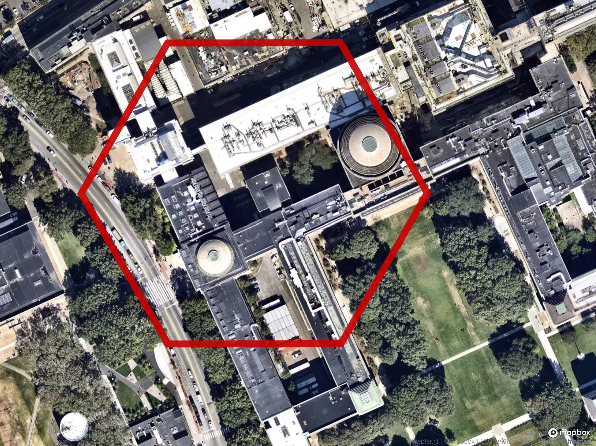
For example, the index "4d950064:7fcd8100" encodes a hexagon around MIT’s Great Dome:
4d95represents theHexSystem’s center at(lon, lat) = (-71, 42). Conveniently, there are 361 possible longitudes (-180 to 180) and 181 possible latitudes,361 * 181possible centers barely fits in a 16 bit unsigned integer.0064, i.e. 100 in hexadecimal, is theHexSystemcell size.7fcdand8100are theqandrcomponents of theHexCell’s axial coordinates in hexagon space.
Final thoughts
H3 and S2 are amazing libraries. As I’ve explored grid system design space, I haven’t encountered any obvious ideas for making better general purpose global grid systems. Nonetheless, I suspect many people—certainly true for us at Zoba—don’t really need a global grid system; they just need a convenient way to build local grid systems. For that use case, I suspect it’s possible to do better than the tradeoffs offered by H3/S2. And while I’m of course super biased, I think HexGeoGrids.jl is a step in approximately the right direction.
-
Maps in this post are made with Kepler, an open source tool for visualizing geospatial data. The underlying maps come from Mapbox and, were they dynamic embeds rather than just screenshots, would include the clickable links © Kepler.gl, © Mapbox, © OpenStreetMap and Improve this map. ↩


